![]()
Building a Weatherproof Housing
for the FMV1 Microphone (Page 1)
by Matt M.
![]()
Here's a list of the parts I used to build the housing for the mic :
Here's the list of the tools I used to build and test it :
![]()
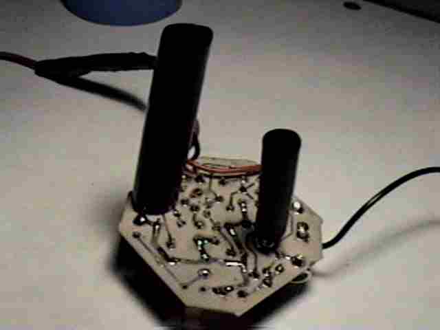
The two pictures below show the first steps in building the housing. These involve waterproofing the circuit board. In the photos you see two black tubes protuding from the circuit board. They are sections of plastic "heat shrink" tubing. The first picture short sections tubing are slid loosely over the mic element and the tuning screw. The second picture shows what it looks like after a small flame is waved around the tubing. The tubes shrink and contrict tightly around the mic and tuning pot. The purpose of the tubing is to protect the mic and screw from the wax that will be poured around the rest of the circuit board, and as water tight sleeve to prevent moisture from getting down underneath the mic and screw where corrosion could build unseen.
After the messy steps with the liquid wax are complete these tubes will be cut so only the top of mic and screw are exposed. [Note : heat shrink tubing is available at Radio Shack.]

![]()
The next step is to drip melted wax all over the circuit board so that it is completely covered. The purpose of the wax is to protect the electronic parts from rust and corrosion. It also eliminates air cavities that might become occupied by insects.
I used regular candle wax for this. To melt the wax I used an electric soldering iron from Radio Shack. The soldering iron was also good for controlling where the wax drops would fall. The wax drops must not fall onto the head of the mic or tuning screw. Otherwise, the wax doesn't interfere with the workings of the electronic circuitry.
The second picture shows me dripping the wax into blue plastic cup that comes with the mic kit. It's just big enough to set the circuit board into so that the mic and tuning screw will protrude above the brim of the cup.
The open ends of the heat shrink tubes should be covered with scotch tape while working with the hot wax to prevent drops of wax from falling inside the tubes and onto the sensitive parts. Don't forget to take this precaution. The reason I know it's important is because I didn't do it the first time and a drop of wax fell onto the mic head, which basically ruined it. I had to order a replacement mic element, which put the whole project on hold for a couple of weeks while I waited for the part to arrive in the mail ... It was a real pisser. Don't let it happen to you.

![]()
The two pictures below show the cup filled to the brim with wax. Notice the wires sticking out the wax. The single wire on one side is the antenna wire. The double wire on the other side is the battery connection wire. The end of the battery wire has a connector pad for a 9 volt battery.
Notice the battery wire has a bulging section in the middle. The bulging section is where I made an extension for the battery wire. A 9volt battery pad (with about 4 inches of black and red wire leads attached) comes with the mic kit but it's a low quality part. I bought a better pad (with wires) from Radio Shack for about a dollar. This battery wire will be tugged and pulled every time the 9 volt battery is replaced so it has to made to withstand it. To make the extension splice extra sturdy I used a piece of heat shrink tubing to cover the soldered wires then wrapped the whole thing with electricians tape. That may seem overboard but you may discover that if something goes wrong with the mic it's usually a problem with the battery wire being loose or corroded. The second most common problem is damage or corrosion to the tuning screw (more about that later).

![]()
The two pictures below show the plastic funnel which is the main part of the housing. Before putting the cup inside the funnel I made a strap for the housing by stringing a leather boot lace through the openning of the funnel and tying a knot on one end so it wouldn't pull through. You can also see in the first picture how I had a plastic ring near the knot to make sure the knot wouldn't pull through funnel hole. The leather lace is pulled tight then the knot is covered with hot glue from a glue gun. The hot glue has to throughly covered the knot side of the funnel whole, and it has to be injected into the other end of the funnel. The purpose of filling the funnel hole with hot glue is to both secure the strap and to make the funnel hole completely water tight.
Once the funnel hole is completed filled with glue the cup is then placed inside the funnel so the mic head is pointing out the wide mouth of the funnel as shown in the second photo below. The cup is held in place with more hot glue around the base of the cup.
Some people assume the function of the funnel is for parabolic reflection of sound toward the mic. That's not the purpose of the funnel at all. The funnel shape is purely intended as a rain and snow hood, and to a lesser extent a wind guard. When the mic is used in the field it is hung in a tree with the mouth of the funnel pointing straight down at the ground. It is not meant to be pointed sideways toward sources of sound, nor does it need to be. The mic is sensitive enough to pick up distant sounds from all directions in that position.

![]()
Next Page : Building the mic housing, page 2.
![]()
Previous Page : Intro to the mic pages.
![]()
Bigfoot
Field Researchers' Homepage
Submit a report,
an article, or comments.